
Many electrical designs utilize components with a large number of connections, and keeping track of which connections have already been used in a design can be tricky. Using pinlists with AutoCAD Electrical is the most efficient way to track both used and available pins, as well as keeping the connections of any device organized by type. They are useful for error checking, maintaining accurate connection information, and ensuring that pins that are supposed to go together stay together. Pinlists can be used for all kinds of devices, and in the substation design world we see them used most often with relays and test switches.
At the most basic level, pinlists are long strings of text, or lists of lists, that contain connection data for a given component. The pinlists are stored in the catalog database, where they are given unique, manufacturer-based tables. For example, the pinlists for all of your SEL components would not be found in the PR table; rather, they would be found in the _PINLIST_SEL table (assuming that “SEL” is what you used in the MANUFACTURER field). The pinlist fields are editable within the Access or SQL database, as well as within the catalog browser inside AutoCAD Electrical. I recommend typing your pinlists in a text editor like Notepad, and then copying them into your database. Alternatively, some of my clients have developed pinlist builders using Excel, which is a great way to do it for those who can maximize the powers of Excel.

Building Pinlists
A pinlist entry can have three types of information, and takes the following form: TYPE, TERM01, TERM02, *DESCRIPTION. The type of contact must always be the first item in a pinlist entry, and AutoCAD Electrical has built-in values associated with these contact types. A ‘1’ is used for normally open contacts, ‘2’ is for normally closed, ‘3’ is for NONC, and ‘4’ is used for custom contact types. The custom contact type is frequently used within substation design, and the SDSIC has published a list of recommended pinlist types, which you can see below. When using custom pinlist types, be sure to use the attribute PINLIST_TYPE on your child symbols, with the desired type set as the default value of this attribute. (Parent symbols should use the attribute COILPIN, which can be left blank.)
SDSIC Custom Connection Types
- 4DI : Digital Inputs
- 4DO : Digital Outputs
- 4DIP : Digital Inputs (Polarity Sensitive)
- 4DOP : Digital Outputs (Polarity Sensitive)
- 4CC : Current Coils
- 4PT : Potential Coils
- 4TE : Telecom Equipment
- 4TCI : Test Switch Current In
- 4TCO : Test Switch Current Out
- 4TP : Test Switch Potential
- 4TT : Test Switch Trip
- 4PB : Pushbuttons
- 4LT : Lights
- 4DC : DC Monitor
- 4NM : Terminals
The second element of a pinlist entry is the pin itself. The pins should be placed in order, separated by commas with no spaces between the text and comma. As many pins as are needed can be added to the individual entry. For example, in the second line of the image above you will see six pins, Z01-Z06, listed immediately after the type 4CC. The symbol for this particular component is built with six TERM## attributes, and the values Z01-Z06 will be inserted, in order, into the attributes TERM01-TERM06. This is an important detail to remember as you put together your pinlists: the second element in any pinlist entry corresponds to TERM01, the third element goes with TERM02, and so on.
Within the substation design world, it is becoming common practice to use a third terminal attribute to hold the input/output number for a given relay contact. (This practice is also commonly used to hold the pole letter on test switches.) This benefits the user by keeping the pins and in/out number (or pole letter) together, significantly reducing the likelihood of user error. In order for this strategy to work, however, a corresponding XTERM attribute must be added to the symbol in question. It is advised that this attribute be called X0TERM03, with the first ‘0’ indicating an angled contact point, and that this attribute be placed somewhere random, away from obvious wire connection points. When this strategy is implemented, the pinlist entry would look something like this: 4DO,A01,A02,OUT101.
The final element of a pinlist entry is the description. This portion is optional, but if used, must be preceded by an * character. In the image below you will see a typical pinlist window. This particular pinlist has used descriptions, which are shown before the pins in the window on the left. For example, the entry at the top of that window looks like this: 4DO,Z15,Z16,*TRIP.
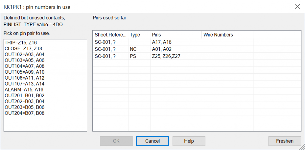
When building your pinlists, be sure to use a ‘;’ between entries, and remember that you don’t need one at the end. So a very short pinlist might look like this:
4DO,A01,A02,OUT101;4DOA03,A04,OUT102;4DI,A05,A06,IN101;4DI,A07,A08,IN102
Once you have one done, copy and paste it into the appropriate field either in your catalog database (Access or SQL) or directly from the catalog browser in AutoCAD Electrical. While you have the catalog browser open, go ahead and add the pins of your parent symbol (for relays, this is typically the power supply) into the COILPINS field. You don’t have to add these pins to your pinlist, but it’s helpful to put them directly into your catalog.
Building pinlists can be tedious, but it is a one-time investment of time that will pay dividends on future projects. Just remember: You only have to build that 487B pinlist once!
Using Pinlists
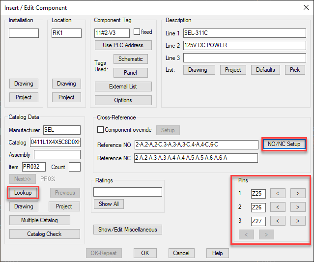
Using pinlists is incredibly easy and rewarding. Start by inserting the parent schematic symbol – the most typical case would be the power supply of an SEL relay. In the Insert/Edit Component dialogue box, add the appropriate catalog data using the Lookup button. If your catalog database is up to date, this will automatically insert the pins for this device, as well as add the pinlist data in the NO/NC Setup window.
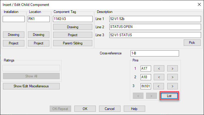
After inserting the parent component, move on to adding child contacts. Once you have linked the child to the parent, you can select the List button in the bottom right-hand corner to select the contacts from the pinlist window. This window, a version of which is shown above, will show you which sets of pins are available, and which have already been used. Simply pick the group of pins from the list of available pins, and the software will update the contact automatically.
Building and using pinlists is a microcosm of the AutoCAD Electrical experience. There’s a little more work on the front end, a little more tedium to endure one time, but there is significant return on investment the rest of the way. Large components are so much easier to deal with when using pinlists because you don’t have to keep track of what contacts have been used where – the software does all of that for you! Not only do you save time in the drafting phase of the project, but QAQC goes quicker because there are fewer errors on the major components; and even if a change has to be made, it’s only a matter of three easy clicks.
If you ever need any assistance with pinlists or anything else related to AutoCAD Electrical, please don’t hesitate to contact us. We would love to make you successful!





Leave a Comments