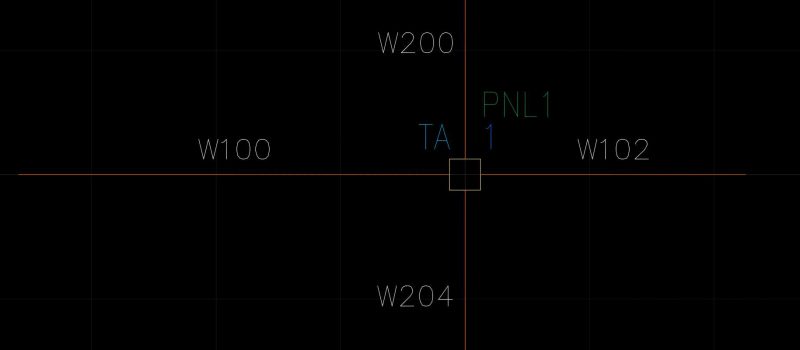
One common situation in substation designs is connecting multiple wires with different wire numbers to the same terminal. The design calls for the wire number to break as it passes through the terminal point, even though the drawing might not show all of this information. AutoCAD® Electrical allows you to connect multiple wires with different wire numbers to the same terminal. The trick is using the correct terminal symbol.
It’s important to know how AutoCAD® Electrical handles schematic symbol block names. You can read all the details about schematic symbols here, but when it comes to terminal symbols, this is what you need to know. The first two characters in the file name must be either HT (for horizontal terminals) or VT (for vertical terminals). The third character is the one that determines what kind of terminal it is. To create a terminal that does not break the wire number, use a ‘0’ in that third position. But if you need a terminal that does break the wire number, the third character should be a ‘1’. So a square terminal block that breaks the wire number might have a name of HT10_SQUARE.dwg, VT1001_SQ.dwg, or whatever fits your needs.
This seems like basic information, but if you don’t know about the schematic symbol naming convention, you won’t know how to wire up these terminals. Before I had this information, I spent a couple very frustrating hours naming and renaming wires, only to have my entire wire network get all screwed up! The simplest solution, of course, was to swap an HT1* symbol in for the HT0* symbol that was already on the drawing. This little tip has been a game changer in my design philosophy.

One of my clients only wants “external” wires to have wire numbers. This means that every wire that changes LOC (location) code from one end to the other needs to be numbered. When this is drafted, however, the wire most likely runs from something like a protection relay in location 1, passes through two terminals (one in location 1 and the other in location 2), and ends up in something like a control relay in location 2. When drawn, this looks like a single wire segment with two terminals on it. However, if the two terminals are wire-breaking terminals, the segment between them can be assigned a wire number, and the two segments on either side will remain blank.
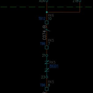
In the example in the image to the right, the wire runs off of a protection relay on RK6 to terminal TB12-10 on that same rack. Then it runs through cable C074 on the black conductor to terminal TB6-7 on RK5. From there it goes to a lockout relay on that rack. What you can’t see is that both of those terminals break the wire number, and only the segment with the cable marker on it has an assigned wire number. All of that information can be hidden so as not to clog up your schematic design, but the wire number will appear when the wiring diagram is annotated.
To sum up, in order to connect wires with different wire numbers to the same terminal you need to use a terminal with the file name HT1* or VT1*. The ‘1’ in the third place of the file name tells AutoCAD® Electrical that this terminal breaks the wire number, so that wires terminating at any other point on this terminal can carry a different wire number, or no number at all.


I am trying to use this feature, but in a little bit different way. I am trying to have the wire that leaves the panel have the same wire number as what connects to the terminal inside the panel, just add the installation location. That way in the panel I can have wire number 20201 connecting to a terminal, then 20201-1 leaves the panel regardless of the fact that I am on page 57, line 13 and normally that wire would be labeled 57131-1. I am not able to find a way to do this…
Hi Cristian, my line of work is substation design, and in substation we do not use automatic wire numbering – we do it all manually. If you are adding wire numbers manually, this should be as easy as editing the wire number in question. I’m not sure how to do it any other way, unfortunately.