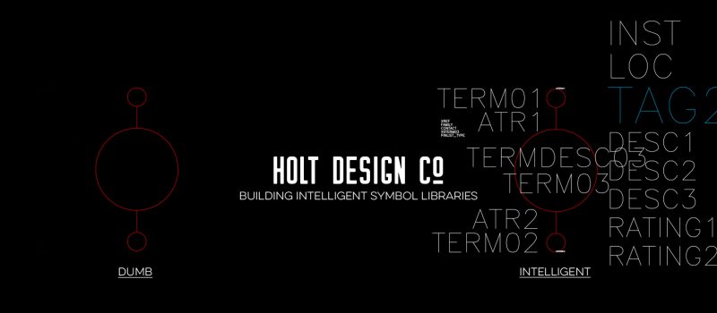
More and more utilities and engineering firms are making the switch to AutoCAD Electrical and the SDS Toolkit for P&C substation design. It’s an exciting time for our industry, and while it’s not my place to name names, there are major organizations leading the way toward industry-wide intelligent substation design. But what does it take to make this kind of transition?
One of the biggest hurdles in making the transition to AutoCAD Electrical and the SDS Toolkit is the development of intelligent symbol libraries. AutoCAD Electrical utilizes a blocks+attributes approach, which is what gives it so much of its power and intelligence. And that’s all that an AutoCAD Electrical symbol is: a block with attributes. That may not sound like such a big deal, but a quick scan through a substation drawing set will remind you just how many different symbols you use on a given project, and just how daunting a task it can be to create intelligent symbol libraries.
Some intelligent symbol libraries that I’ve helped to develop in the past have over 800 unique symbols! If you count on an average of 15 minutes to create each symbol (many take less, but there are some that take much, much more), you’re looking at spending up to 200 hours on symbol creation — and that’s if you know what you’re doing! Here are some things to consider as you build your custom, intelligent symbol libraries.
Organization
AutoCAD Electrical looks for two unique symbol libraries: the schematic library and the panel library. At the very least, you’ll need to have all of your schematic symbols stored in the schematic library, and all of your panel symbols (including both front and rear view) in the panel library. It’s important to keep these two basic types of symbols separated.
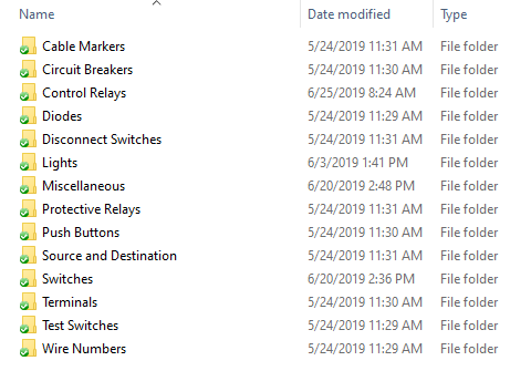
However, if you have 800 symbols or more in your libraries, scanning through all of those files can be a frustrating and time-consuming experience. Several of my clients have decided to break each primary folder down into subfolders organized by families. So all of the schematic protective relays go in one subfolder, all of the fuses in another, and all of the terminals in yet another — you get the idea. The biggest benefit to this approach is that you know exactly where to go to find what you’re looking for. However, you’ll also have to be sure to add each and every subfolder to the library search path lines of your project file — but you only need to do this once, because you can just copy those settings to each new project.
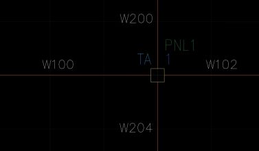
Panel symbols (also called footprints) present an interesting case because there are at least three different types of panel symbols available to you when using AutoCAD Electrical and the SDS Toolkit. There is the front-view symbol that is found on the panel elevation drawing, the rear-view symbol for the wiring diagrams, and the input/output tables that are often placed on schematic drawings, even though they are actually panel symbols. Even if you place each of these blocks into different subfolders, they’ll all need unique names. I’ve found that the simplest solution is to use the following prefixes: TBL_ for tables, PNL_ for panel front-view symbols, and WD_ for wiring diagram symbols.
Attribute Text
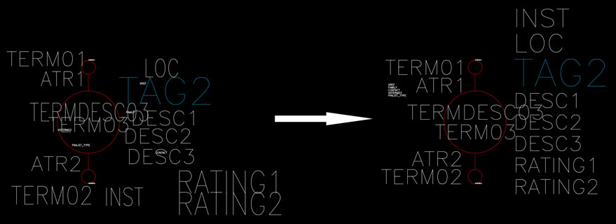
One of the quickest ways to make a substation designer’s head explode is to ask him or her, “Can you just make that text a little bigger?” In almost any other application, changing text sizes is no big deal. But in AutoCAD Electrical, you’re not dealing with lines of text that will auto-format; you’re dealing with individual attributes that have been precisely sized and spaced to find that perfect mix of readability and spatial efficiency. If the text is too small, the workers doing the wiring won’t be able to read it. But if it’s too big, you won’t be able to fit everything on the page. Here are some important questions to lock-in before you get started:
Which font should be used? The default font is romans.shx, but using a .ttf font will give you some cool functionality in your .pdf files. Also keep in mind that a thicker and wider font is going to take up more space. A fixed-width font isn’t a bad idea, but it can also be a space hog. Use the text style window to set all of your attributes to the appropriate text style(s) (standard is WD), and apply the chosen font to that style.
What size should the font be? Common font height for standard attributes is between .08 and .125. You may want some of your attributes, like TAGs or MOUNT, to be larger than others, or even to show as boldface type. The width of the font will also vary between .8 and 1, but keep in mind that there will most likely be cases where you’ll need to squeeze some text to fit it onto the page.
How much space should there be between attributes? This is an important question that doesn’t get asked very often. In my judgment, the “white space” between attributes should be half of the font height. This same distance should also be applied between the edge of the block geometry and the insertion point (assuming left or right justification) of the attribute.
Attribute Templates
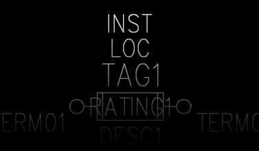
Attribute templates are a great way to keep your symbols looking consistent and professional. You can create attribute templates for each family type, and even make separate ones for parent and child symbols. You can learn more about attribute templates here.
Attribute templates can be inserted via the AutoCAD Electrical Symbol Builder. Alternatively, you can use the INSERT command to drop the attribute template into the DWG file of the symbol itself. It all depends on how you are most comfortable creating your symbols.
Other Stuff
There are a few other things that are worth mentioning quickly. Unless you are predetermining which layers and/or colors certain elements of your symbol are going on, everything on your symbol should be set to Layer 0. There are multiple reasons for this that we don’t have time to get into now, but suffice it to say that this just makes everything cleaner.
Speaking of keeping everything neat and tidy, be sure to run the PURGE command after you have everything on Layer 0. This will get rid of all unused blocks, layers, text styles, and more. Anything that is not purged, like extra layers, for example, will be placed on your drawings when you insert your symbol. So be sure to purge, and then purge again just to make sure!
One final thing you may want to do is go and download the free Holt Design Tools for symbol building, and run the REORDER_ATTDEF command. This will organize all of your attributes into a logical order for display in the Enhanced Attribute Editor window of AutoCAD Electrical.
If you need help building your custom symbol libraries, be sure to contact us. We have a lot of experience getting our clients up and running with AutoCAD Electrical and the SDS toolkit, and we would love the opportunity to help you. Alternatively, if you’re not tied to your existing symbol library and don’t mind potentially changing the look of your drawings, check out the free UPCS symbol library provided by the SDS Industry Consortium. You’ll have to get user credentials, but once you do, you’ll find the library in the Buddy Drive of the Electrical Group.




You hit all key points that, if acted upon from the start, will greatly ease the transition of an existing CAD symbol and standards circuit library from dumb to smart. Then the efficiency, accuracy, and magic all start to kick in. Nice!