info@holtdesignco.com

(419) 367 2263

Menu
  • Home
  • About
  • Holt Design Tools
  • Services
  • Tips & Tricks

Posts Tagged: wires

  • Home
  • Posts Tag: Wires
https://holtdesignco.com/wp-content/uploads/2017/10/Holt-Wires-LISP-Tools-HiRes.mp4

Custom LISP Tools for Wiring

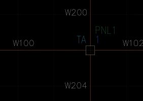
Drafting substation projects is often tedious work because there are so many things that have to be done over and over again. Small, mundane tasks need to be repeated countless times in order for your intelligent substation project to work properly. Fortunately, Holt Design Co. has created some custom LISP tools to make some of these processes much quicker. Two things that you just can’t get around are adding wire numbers and marking external terminal connections. Normally this would involve clicking on each wire that you want to number, adding your custom text, and repeating ad infinitum. Then you have to go back and check the I/E connections of each terminal. This process can be extremely tedious, not to mention mind-numbing. In order to make this process more bearable for one of our clients, we have created two custom LISP tools to blast through these processes. We’re able to use these tools because this client has done something really smart with their template: They created a separate layer for all of their external wires. An external wire begins at a terminal point on one location (say, LOC code = R1) and ends at a point on another location (say, LOC code = R2). The terminal connection points at either end of these wires need to be marked with an E, for external, so that they will annotate on the appropriate side in the wiring diagram. Putting these wires on a separate layer allows the designer to know, at a glance, that this wire needs a cable marker and a wire number, and that the terminals on either end are external. This kind of visual cue is, in our opinion, a great way to design a substation project. The first of our custom LISP tools allow our client to simply click on a wire and swap it to the external wiring layer, as well as automatically mark the connected terminal points as external. Once the designer has inserted and labelled cable markers on these wires, the second tool allows him or her to pick on a wire and automatically sets the wire number based on the cable marker and conductor color. Take a look at the video above to see these custom LISP tools in action.

  • October 2, 2017
  • By andrew
  • AutoCAD® Electrical

Connect Wires with Different Wire Numbers to the Same Terminal

One common situation in substation designs is connecting multiple wires with different wire numbers to the same terminal. The design calls for the wire number to break as it passes through the terminal point, even though the drawing might not show all of this information. AutoCAD® Electrical allows you to connect multiple wires with different wire numbers to the same terminal. The trick is using the correct terminal symbol. It’s important to know how AutoCAD® Electrical handles schematic symbol block names. You can read all the details about schematic symbols here, but when it comes to terminal symbols, this is what you need to know. The first two characters in the file name must be either HT (for horizontal terminals) or VT (for vertical terminals). The third character is the one that determines what kind of terminal it is. To create a terminal that does not break the wire number, use a ‘0’ in that third position. But if you need a terminal that does break the wire number, the third character should be a ‘1’. So a square terminal block that breaks the wire number might have a name of HT10_SQUARE.dwg, VT1001_SQ.dwg, or whatever fits your needs. This seems like basic information, but if you don’t know about the schematic symbol naming convention, you won’t know how to wire up these terminals. Before I had this information, I spent a couple very frustrating hours naming and renaming wires, only to have my entire wire network get all screwed up! The simplest solution, of course, was to swap an HT1* symbol in for the HT0* symbol that was already on the drawing. This little tip has been a game changer in my design philosophy. One of my clients only wants “external” wires to have wire numbers. This means that every wire that changes LOC (location) code from one end to the other needs to be numbered. When this is drafted, however, the wire most likely runs from something like a protection relay in location 1, passes through two terminals (one in location 1 and the other in location 2), and ends up in something like a control relay in location 2. When drawn, this looks like a single wire segment with two terminals on it. However, if the two terminals are wire-breaking terminals, the segment between them can be assigned a wire number, and the two segments on either side will remain…

  • October 2, 2017
  • By andrew
  • AutoCAD® Electrical

© 2020 Holt Design Co., All Rights Reserved.