info@holtdesignco.com

(419) 367 2263

Menu
  • Home
  • About
  • Holt Design Tools
  • Services
  • Tips & Tricks

Posts Tagged: symbols

  • Home
  • Posts Tag: Symbols

Holt Design Tools for Designing Symbols

I’m pleased to offer a great set of tools for AutoCAD Electrical symbol building – for free! These tools are designed with substation designers in mind, allowing them to create large-scale symbols (think SEL relay wiring diagram symbols) with ease and efficiency. Here’s a brief glimpse of what’s included. IAN – This tool allows users to automatically increment attribute names, so that TERM01 becomes TERM02 with just a single click! IAV – Similar to IAN, except that instead of incrementing attribute names, this tool increments attribute values. CHA_DIR – This tool lets users quickly and painlessly change the direction of attributes like X1TERM01. That means you can change X1TERM01 to X4TERM01 with just a click! REORDER_ATTDEF – In the Enhanced Attribute Editor inside of AutoCAD Electrical, attributes appear in the order in which they were placed on the symbol drawing. But with this tool, attributes are reordered so that they appear in a logical and functional order. AGAP – This tool creates a user-defined gap between attributes, making symbols look clean and professional. Full documentation is included with the download. Just click on the link to download the .zip file, and then extract it in a convenient location on your local drive. Open any AutoCAD Electrical drawing, and the file holtdesign.fas to the Startup Suite by using the command APPLOAD. Now the file will automatically load with every new drawing you open. We’re confident that you’re going to love these tools, and that they will make symbol building so much more fun and efficient! Note (11-28-18): The design tools have been updated to correct an issue with the AGAP tool requiring the user to be running the SDS toolkit in AutoCAD Electrical.

  • October 9, 2018
  • By andrew
  • AutoCAD® Electrical

Connect Wires with Different Wire Numbers to the Same Terminal

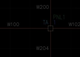
One common situation in substation designs is connecting multiple wires with different wire numbers to the same terminal. The design calls for the wire number to break as it passes through the terminal point, even though the drawing might not show all of this information. AutoCAD® Electrical allows you to connect multiple wires with different wire numbers to the same terminal. The trick is using the correct terminal symbol. It’s important to know how AutoCAD® Electrical handles schematic symbol block names. You can read all the details about schematic symbols here, but when it comes to terminal symbols, this is what you need to know. The first two characters in the file name must be either HT (for horizontal terminals) or VT (for vertical terminals). The third character is the one that determines what kind of terminal it is. To create a terminal that does not break the wire number, use a ‘0’ in that third position. But if you need a terminal that does break the wire number, the third character should be a ‘1’. So a square terminal block that breaks the wire number might have a name of HT10_SQUARE.dwg, VT1001_SQ.dwg, or whatever fits your needs. This seems like basic information, but if you don’t know about the schematic symbol naming convention, you won’t know how to wire up these terminals. Before I had this information, I spent a couple very frustrating hours naming and renaming wires, only to have my entire wire network get all screwed up! The simplest solution, of course, was to swap an HT1* symbol in for the HT0* symbol that was already on the drawing. This little tip has been a game changer in my design philosophy. One of my clients only wants “external” wires to have wire numbers. This means that every wire that changes LOC (location) code from one end to the other needs to be numbered. When this is drafted, however, the wire most likely runs from something like a protection relay in location 1, passes through two terminals (one in location 1 and the other in location 2), and ends up in something like a control relay in location 2. When drawn, this looks like a single wire segment with two terminals on it. However, if the two terminals are wire-breaking terminals, the segment between them can be assigned a wire number, and the two segments on either side will remain…

  • October 2, 2017
  • By andrew
  • AutoCAD® Electrical

When to use the INST attribute

One of the most common questions we get about using AutoCAD® Electrical symbols is what to do with the INST attribute. It seems important, and you would think that it ought to carry a value of some kind. But that’s not always the case. In fact, you will most likely never need to use the INST attribute in any of your projects. Let me explain. Just like the LOC attribute stands for LOCATION, the INST attribute stands for INSTALLATION. The installation code is the next layer of component identification above location. For example, if you have a protection relay R1 in location PNL2 in installation N, the software would identify that component as N+PNL2+R1. (The image on the left shows where this option is activated in the Project Properties menu. It is highly recommended that this option is always on for all of your projects.)  As far as AutoCAD Electrical is concerned, the name of your component is a concatenation of three attributes: INST + LOC + TAG. So it might seem like a good idea to assign a value for the INST attribute in all of your drawings, right? Probably not. The installation code is only meant to be used on large substation projects with multiple installations of (essentially) the same system. If your project has two or more control houses (for example, a north side and a south side), then you probably need to set the INST code. Otherwise, it’s perfectly acceptable to leave it blank. There’s no need to add another layer of complexity to an already complex project. Using unnecessary installation codes can cause confusion for the designer and the software. The LOC and TAG attributes are all that are needed to identify the components in any project for most users. Adding another layer of identification only creates the possibility for more errors. As always, it’s better to keep things simple. Unless your project has multiple control houses, ignore the INST attribute. But if your project does require multiple, identical design copies, we recommend using a sensible code. How is each identical design copy labelled? Consider using that to come up with a short, unique INST code for each design copy.

  • September 27, 2017
  • By andrew
  • AutoCAD® Electrical

© 2020 Holt Design Co., All Rights Reserved.