One of the best tools in the SDS Toolkit for AutoCAD Electrical is the Annotation tool. This tool takes the wire connection data from the schematic drawings in your project and pushes it out to the corresponding components on the wiring diagrams. This is a significant time-saving tool, and is one of the best features of the SDS Toolkit. But what do you do when you have annotation problems? How do you resolve incorrect annotation data without manually typing it in?
1. Rebuild the Database
The very first thing I do to resolve annotation problems is rebuild the database. To do this, either click the “Rebuild Dbase” icon from the SDS Tools ribbon, or type AEREBUILDDB at the command prompt. Depending on the size of your project, this could take up to a couple of minutes. By doing this, you are making sure that the database, from which the annotation data is drawn, is up to date. The annotation tool will freshen the database every time it is run, but it doesn’t rebuild the entire thing from scratch. Sometimes you need to do this to pick up changes that have been made in the past.
2. Check the INST+LOC+TAG values

If rebuilding the database doesn’t solve the problem, be sure to check the INST, LOC, and TAG attributes on both the schematic and panel symbols. In fact, if nothing annotates on the wiring diagram symbol, this should be the first thing you check. One easy way to check this is to SURF on the panel symbol and see what else comes up. If there are no other components found, then you know there is a mismatch somewhere along the INST+LOC+TAG string.
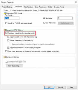
Incidentally, if you are getting unexpected annotation, or way too much data on your annotation, you may want to check your project properties menu. In the Components tab of this menu, there is a very important checkbox that you need to activate: Combined Installation/Location tag mode. This should always be checked for all of your projects because it tells the software to identify each component by its INST+LOC+TAG attribute string. If this is unchecked, the software will treat all components with the same TAG value (think terminal blocks) as the same component.
3. Confirm the Wire Sequence

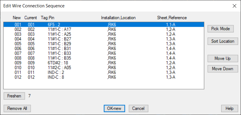
If the annotation you are seeing on your wiring diagrams is good, but just in the wrong order, you’ll want to go back to the schematic drawings and re-order the wire sequence. There is a tool for this on the SDS Tools ribbon, and all you have to do is click on a wire, and then move the various components up or down in the list until things are ordered correctly. Keep in mind that the items at the top and bottom of the list will only show the one component they are directly tied to, but all the components in the middle will show two connections. Another thing to be aware of is that if a component is in the middle of a wire sequence, and it has two wires connected to that same pin, it will show three connections. Sometimes it may be necessary to redraw the wiring on the schematic so as to get the desired annotation.
Another wiring-related issue you may run into happens when you see ??-? on your annotation. Typically, these appear when a wire leaves one pin on a certain component, but does not arrive at another pin on any other component. If you have a piece of wire that just stops without connecting to another component, consider moving that piece to a non-wiring layer. If you are using source/destination arrows, try running the Update Src/Dest command from the SDS Tools menu, and double check to make sure that the SIGCODE matches between the appropriate source and destination arrows. Finally, check to make sure that none of your wires are polylines. If you find a polyline, use the EXPLODE command to reduce it to a regular line.
4. Check terminals for correct Internal/External Assignments

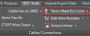
If the problem is with terminal annotation showing up on the wrong side of the terminal strip, you have mismatched the internal and external wire connection assignments. Every wire connection attribute on a terminal has a corresponding X#TERMDESC attribute that carries one of three values: blank, I, or E. To change these values, use the Term: Mark Ext Conn tool on the SDS Tools ribbon. This tool also has an internal and a blank function. If you want to get a quick look to see what the connection assignments are for a given terminal, use the Rollover tool. (This tool also works with term strips on wiring diagrams.)
5. Investigate the Symbols
If all else fails, take a long look at the schematic symbol that isn’t annotating correctly. Make sure that the X#TERM## and TERM## attributes all match up. When working with a symbol recently, I found that the 6 terminals were numbered correctly (TERM01 – TERM06), but the X#TERM## attributes were not: they were numbered X#TERM07 – X#TERM12. These wire connection attributes have to match the terminal number attributes in order for the annotation to go to the right place.
Another thing to look out for is a space character either before or after the terminal number, either on the schematic drawing or the wiring diagram symbol. For example, if your SEL wiring diagram symbol has a pin with a value of “A01 ” (notice the space after ‘1’), but the corresponding schematic pin value is “A01”, it will not annotate. This, and other typos like it, is a very subtle mistake that can easily be overlooked.
6. Contact Us
If you’re still experiencing annotation problems, contact us and we’ll try to get you sorted out. In addition to solving your annotation problems, we can show you how to use this tool to achieve all kinds of interesting results.


Leave a Comments